ESP32 ADC
目录 |
1 Overview
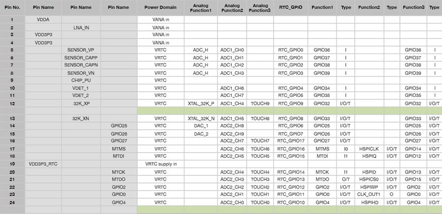
ESP32 integrates 12-bit SAR ADCs and supports measurements on 18 channels (analog enabled pins).
Some of these pins can be used to build a programmable gain amplifier which is used for the measurement of small analog signals. (IO36 and IO39 on Quantum board)
The ULP-coprocessor in ESP32 is also designed to measure the voltages while operating in the sleep mode, to enable low power consumption; the CPU can be woken up by a threshold setting and/or via other triggers.
All ADC pins of ESP32:
Quantum Board use the IO36, IO39, IO34, IO35, IO14, IO12, IO13, IO15 only
2 API
In librtc.a:
enum adc1_pad {
    ADC1_GPIO36 = 0,
    ADC1_GPIO37,
    ADC1_GPIO38,
    ADC1_GPIO39,
    ADC1_GPIO32,
    ADC1_GPIO33,
    ADC1_GPIO34,
    ADC1_GPIO35
};

enum adc1_atten {
    ADC1_ATTEN_0DB = 0,     /* 0 ~ 1V can be measured */
    ADC1_ATTEN_3DB,         /* 0 ~ 1.4V can be measured */
    ADC1_ATTEN_6DB,         /* 0 ~ 2V can be measured */
    ADC1_ATTEN_12DB         /* 0 ~ 4V can be measured */
};

/* Range of the return value is [0, 4096] */
uint32_t adc1_read(enum adc1_pad pad, enum adc1_atten att);

/*
 * Read the amp adc, IO36 as the ADC_PRE_AMP
 * make sure connecting a 270pF cap from
 * esp32_pin5 to esp32_pin6
 */
uint32_t adc1_amp_read();
3 Quick Start
3.1 Build
$ sudo apt-get install git wget make libncurses-dev flex bison gperf python python-serial
$ wget https://dl.espressif.com/dl/xtensa-esp32-elf-linux32-1.22.0-59.tar.gz
$ mkdir -p toolchain
$ tar zxf xtensa-esp32-elf-linux32-1.22.0-59.tar.gz -C toolchain
$ export PATH=$PATH:`pwd`/toolchain/xtensa-esp32-elf/bin
$
$ git clone --recursive git://github.com/icamgo/esp-idf.git
$ export IDF_PATH=`pwd`/esp-idf
$ cd esp-idf/examples/09_adc_read
$ make menuconfig
$ make -j2
3.2 Connections
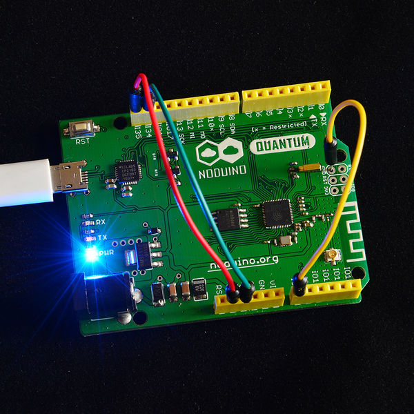
To test the ADC pin of ESP32 on Quantum:
- Connect the Quantum_IO35 to 3V3 (measure the power voltage)
- Connect the Quantum_IO34 to GND (measure the GND voltage)
- Connect the Quantum_IO36 to GND
3.3 Upload
$ make flash
You need to press the RST buttom after uploading the firmware into flash. If you guys do not like to do this please patch the /path/to/esp-idf/components/esptool_py/esptool/esptool.py :
diff --git a/esptool.py b/esptool.py
index 755f4cb..ff92c91 100755
--- a/esptool.py
+++ b/esptool.py
@@ -197,6 +197,12 @@ class ESPLoader(object):
               + '\xc0'
         self._port.write(buf)

+    def reset_to_app(self):
+        self._port.setDTR(False)
+        self._port.setRTS(True)
+        time.sleep(0.05)
+        self._port.setRTS(True)
+
     """ Calculate checksum of a blob, as it is defined by the ROM """
     @staticmethod
     def checksum(data, state=ESP_CHECKSUM_MAGIC):
@@ -1421,7 +1427,6 @@ def dump_mem(esp, args):
         sys.stdout.flush()
     print 'Done!'

-
 def write_flash(esp, args):
     """Write data to flash
     """
@@ -1503,6 +1508,7 @@ def write_flash(esp, args):
     if args.verify:
         print 'Verifying just-written flash...'
         verify_flash(esp, args, header_block)
+    esp.reset_to_app()


 def image_info(args):
Then Quantum can reset to run your app automatically after uploading the firmware into flash
3.4 Checking Output
$ picocom -b 115200 /dev/ttyUSB0
ets Jun  8 2016 00:22:57

rst:0x1 (POWERON_RESET),boot:0x13 (SPI_FAST_FLASH_BOOT)
ets Jun  8 2016 00:22:57

rst:0x10 (RTCWDT_RTC_RESET),boot:0x13 (SPI_FAST_FLASH_BOOT)
configsip: 0, SPIWP:0x00
clk_drv:0x00,q_drv:0x00,d_drv:0x00,cs0_drv:0x00,hd_drv:0x00,wp_drv:0x00
mode:QIO, clock div:1
load:0x3ffc0000,len:0
load:0x3ffc0000,len:920
load:0x40078000,len:3220
ho 0 tail 12 room 4
load:0x40080000,len:260
entry 0x40080034
I (63) heap_alloc_caps: Initializing heap allocator:
I (63) heap_alloc_caps: Region 19: 3FFB45D8 len 0002BA28 tag 0
I (64) heap_alloc_caps: Region 25: 3FFE8000 len 00018000 tag 1
I (74) cpu_start: Pro cpu up.
I (80) cpu_start: Single core mode
I (86) cpu_start: Pro cpu start user code
rtc v118 Oct 19 2016 15:22:11
XTAL 40M
I (121) cpu_start: Starting scheduler on PRO CPU.
Welcome to Noduino Quantum
Try to test the ADC1 pin of the ESP32 ...
ESP32 onchip ADC1 (IO36) = 0
ESP32 onchip ADC1 (IO39) = 0
ESP32 onchip ADC1 (IO34) = 0
ESP32 onchip ADC1 (IO35) = 4095
ESP32 ADC PRE AMP (IO36) = 0

ESP32 onchip ADC1 (IO36) = 0
ESP32 onchip ADC1 (IO39) = 0
ESP32 onchip ADC1 (IO34) = 0
ESP32 onchip ADC1 (IO35) = 4095
ESP32 ADC PRE AMP (IO36) = 0
......
......
4 Hacking
4.1 ibrtc.a
- ADC1
   0x4008b84c <adc1_pad_init>:	entry	a1, 32
   0x4008b84f <adc1_pad_init+3>:	extui	a2, a2, 0, 8
   0x4008b852 <adc1_pad_init+6>:	movi.n	a3, 0
   0x4008b854 <adc1_pad_init+8>:	bgeui	a2, 8, 0x4008b85f <adc1_pad_init+19>
   0x4008b857 <adc1_pad_init+11>:	l32r	a3, 0x4008b848
   0x4008b85a <adc1_pad_init+14>:	addx4	a2, a2, a3
   0x4008b85d <adc1_pad_init+17>:	l32i.n	a3, a2, 0
   0x4008b85f <adc1_pad_init+19>:	mov.n	a10, a3
   0x4008b861 <adc1_pad_init+21>:	movi.n	a11, 0
   0x4008b863 <adc1_pad_init+23>:	call8	0x4008cd84 <rtc_pads_pu>
   0x4008b866 <adc1_pad_init+26>:	mov.n	a10, a3
   0x4008b868 <adc1_pad_init+28>:	movi.n	a11, 0
   0x4008b86a <adc1_pad_init+30>:	call8	0x4008cf0c <rtc_pads_pd>
   0x4008b86d <adc1_pad_init+33>:	mov.n	a10, a3
   0x4008b86f <adc1_pad_init+35>:	movi.n	a11, 0
   0x4008b871 <adc1_pad_init+37>:	call8	0x4008cbfc <rtc_pads_funie>
   0x4008b874 <adc1_pad_init+40>:	mov.n	a10, a3
   0x4008b876 <adc1_pad_init+42>:	movi.n	a11, 0
   0x4008b878 <adc1_pad_init+44>:	call8	0x4008ca74 <rtc_pads_slpie>
   0x4008b87b <adc1_pad_init+47>:	mov.n	a10, a3
   0x4008b87d <adc1_pad_init+49>:	movi.n	a11, 0
   0x4008b87f <adc1_pad_init+51>:	call8	0x4008c8e8 <rtc_pads_slpoe>
   0x4008b882 <adc1_pad_init+54>:	retw.n
   0x4008b884 <adc1_read>:	entry	a1, 32
   0x4008b887 <adc1_read+3>:	extui	a2, a2, 0, 8   <--- 1st parameter of adc1_read, pin used to measure the voltage
   0x4008b88a <adc1_read+6>:	or	a10, a2, a2
   0x4008b88d <adc1_read+9>:	call8	0x4008b84c <adc1_pad_init>
   0x4008b890 <adc1_read+12>:	extui	a3, a3, 0, 8
   0x4008b893 <adc1_read+15>:	mov.n	a10, a2        <--- 1st parameter of adc1_read, it's uint8_t
   0x4008b895 <adc1_read+17>:	mov.n	a11, a3        <--- 2nd parameter of adc1_read, it's uint8_t
   0x4008b897 <adc1_read+19>:	movi.n	a12, 2         <--- 3rd parameter of adc1_read_test, it's 2
   0x4008b899 <adc1_read+21>:	call8	0x4008b0b4 <adc1_read_test>
   0x4008b89c <adc1_read+24>:	mov.n	a2, a10
   0x4008b89e <adc1_read+26>:	retw.n
   0x4008b8a0 <adc1_amp_read>:	entry	a1, 32
   0x4008b8a3 <adc1_amp_read+3>:	movi.n	a10, 0
   0x4008b8a5 <adc1_amp_read+5>:	call8	0x4008b84c <adc1_pad_init>
   0x4008b8a8 <adc1_amp_read+8>:	movi.n	a10, 0
   0x4008b8aa <adc1_amp_read+10>:	mov.n	a11, a10
   0x4008b8ac <adc1_amp_read+12>:	movi	a12, 0x400
   0x4008b8af <adc1_amp_read+15>:	movi.n	a13, 1
   0x4008b8b1 <adc1_amp_read+17>:	movi.n	a14, 4
   0x4008b8b3 <adc1_amp_read+19>:	call8	0x4008b220 <adc1_amp_read_full>
   0x4008b8b6 <adc1_amp_read+22>:	mov.n	a2, a10
   0x4008b8b8 <adc1_amp_read+24>:	retw.n
ADC2:
   0x4008b888 <adc2_pad_init>:	entry	a1, 32
   0x4008b88b <adc2_pad_init+3>:	extui	a2, a2, 0, 8
   0x4008b88e <adc2_pad_init+6>:	movi.n	a8, 9
   0x4008b890 <adc2_pad_init+8>:	movi.n	a3, 0
   0x4008b892 <adc2_pad_init+10>:	bltu	a8, a2, 0x4008b89d <adc2_pad_init+21>
   0x4008b895 <adc2_pad_init+13>:	l32r	a3, 0x4008b884
   0x4008b898 <adc2_pad_init+16>:	addx4	a2, a2, a3
   0x4008b89b <adc2_pad_init+19>:	l32i.n	a3, a2, 0
   0x4008b89d <adc2_pad_init+21>:	mov.n	a10, a3
   0x4008b89f <adc2_pad_init+23>:	movi.n	a11, 0
   0x4008b8a1 <adc2_pad_init+25>:	call8	0x4008cd38 <rtc_pads_pu>
   0x4008b8a4 <adc2_pad_init+28>:	mov.n	a10, a3
   0x4008b8a6 <adc2_pad_init+30>:	movi.n	a11, 0
   0x4008b8a8 <adc2_pad_init+32>:	call8	0x4008cec0 <rtc_pads_pd>
   0x4008b8ab <adc2_pad_init+35>:	mov.n	a10, a3
   0x4008b8ad <adc2_pad_init+37>:	movi.n	a11, 0
   0x4008b8af <adc2_pad_init+39>:	call8	0x4008cbb0 <rtc_pads_funie>
   0x4008b8b2 <adc2_pad_init+42>:	mov.n	a10, a3
   0x4008b8b4 <adc2_pad_init+44>:	movi.n	a11, 0
   0x4008b8b6 <adc2_pad_init+46>:	call8	0x4008ca28 <rtc_pads_slpie>
   0x4008b8b9 <adc2_pad_init+49>:	mov.n	a10, a3
   0x4008b8bb <adc2_pad_init+51>:	movi.n	a11, 0
   0x4008b8bd <adc2_pad_init+53>:	call8	0x4008c89c <rtc_pads_slpoe>
   0x4008b8c0 <adc2_pad_init+56>:	retw.n

   0x4008b8c4 <adc2_read>:	entry	a1, 32
   0x4008b8c7 <adc2_read+3>:	extui	a2, a2, 0, 8
   0x4008b8ca <adc2_read+6>:	or	a10, a2, a2
   0x4008b8cd <adc2_read+9>:	call8	0x4008b888 <adc2_pad_init>
   0x4008b8d0 <adc2_read+12>:	extui	a3, a3, 0, 8
   0x4008b8d3 <adc2_read+15>:	mov.n	a10, a2
   0x4008b8d5 <adc2_read+17>:	mov.n	a11, a3
   0x4008b8d7 <adc2_read+19>:	call8	0x4008b4b0 <adc2_read_test>
   0x4008b8da <adc2_read+22>:	mov.n	a2, a10
   0x4008b8dc <adc2_read+24>:	retw.n
4.2 ADC Registers
In components/esp32/include/soc/saradc_reg.h
#define DR_REG_SARADC_BASE                      0x3ff48800

#define SARADC_SAR_READ_STATUS1_REG          (DR_REG_SARADC_BASE + 0x0004)
/* SARADC_SAR1_READER_STATUS : RO ;bitpos:[31:0] ;default: 32'h0 ; */
#define SARADC_SAR_MEAS_WAIT1_REG          (DR_REG_SARADC_BASE + 0x0008)
/* SARADC_SAR_AMP_WAIT2 : R/W ;bitpos:[31:16] ;default: 16'd10 ; */
#define SARADC_SAR_MEAS_WAIT2_REG          (DR_REG_SARADC_BASE + 0x000c)
/* SARADC_SAR2_RSTB_WAIT : R/W ;bitpos:[27:20] ;default: 8'd2 ; */
#define SARADC_SAR_MEAS_CTRL_REG          (DR_REG_SARADC_BASE + 0x0010)
/* SARADC_SAR2_XPD_WAIT : R/W ;bitpos:[31:24] ;default: 8'h7 ; */
#define SARADC_SAR_READ_STATUS2_REG          (DR_REG_SARADC_BASE + 0x0014)
/* SARADC_SAR2_READER_STATUS : RO ;bitpos:[31:0] ;default: 32'h0 ; */
#define SARADC_ULP_CP_SLEEP_CYC1_REG          (DR_REG_SARADC_BASE + 0x001c)
/* SARADC_SLEEP_CYCLES_S1 : R/W ;bitpos:[31:0] ;default: 32'd100 ; */
#define SARADC_ULP_CP_SLEEP_CYC2_REG          (DR_REG_SARADC_BASE + 0x0020)
/* SARADC_SLEEP_CYCLES_S2 : R/W ;bitpos:[31:0] ;default: 32'd50 ; */
#define SARADC_ULP_CP_SLEEP_CYC3_REG          (DR_REG_SARADC_BASE + 0x0024)
/* SARADC_SLEEP_CYCLES_S3 : R/W ;bitpos:[31:0] ;default: 32'd40 ; */
#define SARADC_ULP_CP_SLEEP_CYC4_REG          (DR_REG_SARADC_BASE + 0x0028)
/* SARADC_SLEEP_CYCLES_S4 : R/W ;bitpos:[31:0] ;default: 32'd20 ; */
#define SARADC_SAR_START_FORCE_REG          (DR_REG_SARADC_BASE + 0x002c)
/* SARADC_SAR2_PWDET_EN : R/W ;bitpos:[24] ;default: 1'b0 ; */
#define SARADC_SAR_MEM_WR_CTRL_REG          (DR_REG_SARADC_BASE + 0x0030)
/* SARADC_RTC_MEM_WR_OFFST_CLR : WO ;bitpos:[22] ;default: 1'd0 ; */

#define SARADC_SAR_ATTEN1_REG          (DR_REG_SARADC_BASE + 0x0034)
/* SARADC_SAR1_ATTEN : R/W ;bitpos:[31:0] ;default: 32'hffffffff ; */
/*description: 2-bit attenuation for each pad  11:1dB  10:6dB  01:3dB  00:0dB*/

#define SARADC_SAR_ATTEN2_REG          (DR_REG_SARADC_BASE + 0x0038)
/* SARADC_SAR2_ATTEN : R/W ;bitpos:[31:0] ;default: 32'hffffffff ; */
/*description: 2-bit attenuation for each pad  11:1dB  10:6dB  01:3dB  00:0dB*/

#define SARADC_SAR_SLAVE_ADDR1_REG          (DR_REG_SARADC_BASE + 0x003c)
/* SARADC_MEAS_STATUS : RO ;bitpos:[29:22] ;default: 8'h0 ; */

#define SARADC_SAR_SLAVE_ADDR2_REG          (DR_REG_SARADC_BASE + 0x0040)
/* SARADC_I2C_SLAVE_ADDR2 : R/W ;bitpos:[21:11] ;default: 11'h0 ; */

#define SARADC_SAR_SLAVE_ADDR3_REG          (DR_REG_SARADC_BASE + 0x0044)
/* SARADC_TSENS_RDY_OUT : RO ;bitpos:[30] ;default: 1'h0 ; */

#define SARADC_SAR_SLAVE_ADDR4_REG          (DR_REG_SARADC_BASE + 0x0048)
/* SARADC_I2C_DONE : RO ;bitpos:[30] ;default: 1'h0 ; */
/*description: indicate I2C done*/

#define SARADC_SAR_TSENS_CTRL_REG          (DR_REG_SARADC_BASE + 0x004c)
/* SARADC_TSENS_DUMP_OUT : R/W ;bitpos:[26] ;default: 1'b0 ; */
/*description: temperature sensor dump out  only active when reg_tsens_power_up_force = 1*/

/*description: indicate temperature sensor out ready*/

#define SARADC_SAR_TOUCH_CTRL1_REG          (DR_REG_SARADC_BASE + 0x0058)
/* SARADC_HALL_PHASE_FORCE : R/W ;bitpos:[27] ;default: 1'b0 ; */
/*description: 1: HALL PHASE is controlled by SW  0: HALL PHASE is controlled
 by FSM in ULP-coprocessor*/
5 Reference
- For more information please refer to

