Noduino OpenLight EN
目录 |
1 Overview
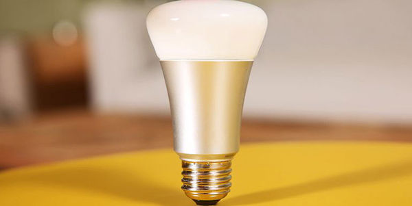
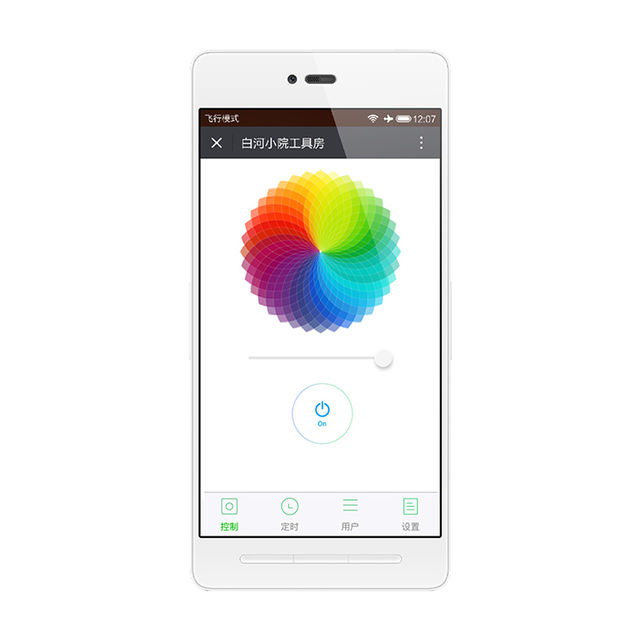
OpenLight Bulb:
OpenLight Controller:
2 Quick Start
- Power on, waiting 8s to light
- Light is flashing slowly in red means waiting for network connection
- If the light is not flashing in red, please turn on and off 3 times, (eg. turn on - light on - turn off, 3 times) the light will be in red gradient for network connection
- Connect mobile to Wifi then scan QR code in WeChat to click “Network Connection”
- Enter WiFi password, click "Connect" then waiting for network connecting complete. (P.S. only 2.4G WiFi is applicable, 5G WiFi and WiFi enterprise-level security certifications are not applicable)
- Complete WiFi configuration, WeChat will be in LAN devices discovery mode. Available devices list will be visible.
- Click the first device then press "Link Device" button to bind the device. (P.S. if the device has been binding, then the button at bottom is "Enter Official Account")
- Finish above steps, please press "Enter Official Account" button then click "My Device" button to find your binding devices list. Click the device to enter control page.
- Note:
- If more people need to control the device, please connect to the same router and scan the same QR code while the device is power on. Click "Device connected and skip" -> "Link Device"->"Enter Official Account" to control smart devices
- To connect the device to another router in same network, please turn on and off the light 3 times and scan the QR code in Wechat to connect the network, binding is not necessary.
- To transfer the device to different place(networks), the light will be in red gradient waiting for networks matching. To connect networks please just scan QR code in WeChat.
- Turn on and off the light 6 times to restore the factory settings
3 API
4 Firmware
4.1 Compile
Getting noduino-sdk:
$ git clone --recursive git://github.com/icamgo/noduino-sdk.git noduino-sdk
Generate toolchain (you need Python 2.7):
$ cd noduino-sdk/toolchain
$ ./gen.py
Compile:
$ cd ../sketch/open-light
$ make
The generated firmware is located in build/ dir named user1.bin annnd user2.bin
Window environment please refer to Getting Started with Noduino SDK on Windows, you can get how to setup the basic developmennt environment
4.2 Upload
4.2.1 Serial
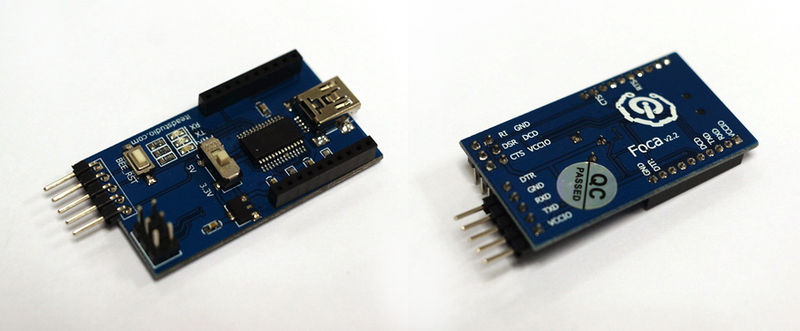
Prepare a USB2UART board, something like FT232RL or CP2102/CP2104:
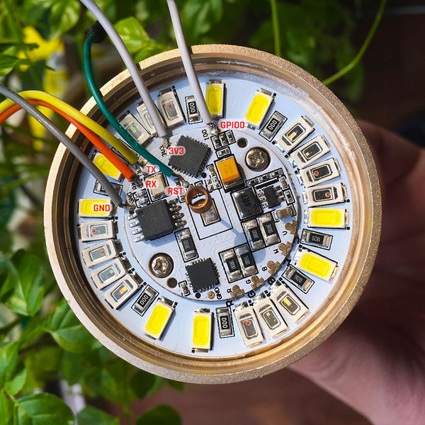
Upload firmware throught serial for OpenLight Bulb:
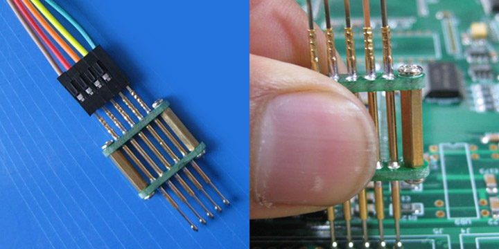
Upload firmware throught serial for OpenLight Controller:
- USB2UART_GND ------> SmartNode_GPIO0 / Bulb_GPIO0
- USB2UAR_GND -----> SmartNode_GND / Bulb_GND
- USB2UAR_RXD -----> SmartNode_TX / Bulb_TX
- USB2UAR_TXD -----> SmartNode_RX / Bulb_TX
Connect USB2UAR_VCC3.3 -----> SmartNode_VCC / Bulb_3V3 at last
ESP8285 will be enter upload mode, we can upload the compiled firmware through serial using following commands in Linux:
$ cd /path/to/noduino-sdk/sketch/open-light
$ make produce ESPPORT=/dev/ttyUSB1
In windows:
$ make produce ESPPORT=COM7
COM7 is your USB2UART device
In MAC OS, maybe it's:
$ make produce ESPPORT=/dev/cu.SLAB_USBtoUART
/dev/cu.SLAB_USBtoUART is your USB2UART device
4.2.2 Online
- Login
- Username: noduino
- password: noduino1234
Click the "Add files", select the user1.bin and user2.bin located in /path/to/noduino-sdk/sketch/open-light/build/
Then click "Start upload" to upload the user1.bin and user2.bin into the server temporaily
5 Hardware
5.1 LED
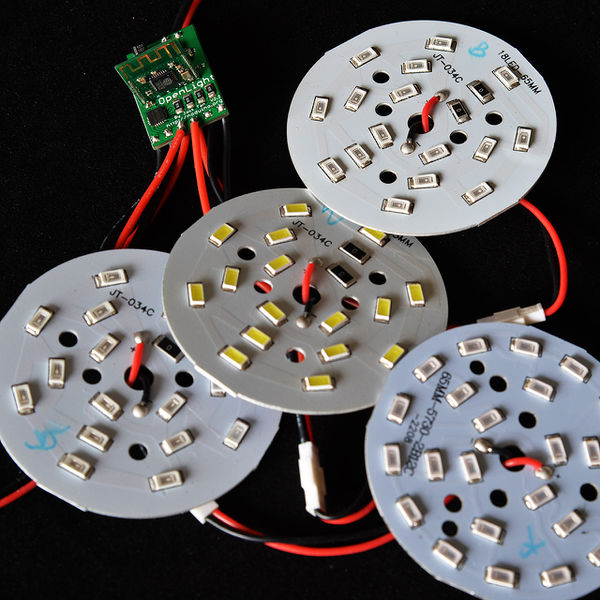
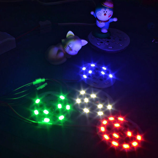
OpenLight 铝基板上,LED 灯珠默认布局为:
- Red LED 6 颗串联,正极接 12V,负极接控制板 R (MY9291 之 OUTA)
- Green LED 4 颗串联,正极接 12V,负极接控制板 G (MY9291 之 OUTB)
- Blue LED 4 颗串联,正极接 12V,负极接控制板 B (MY9291 之 OUTC)
- White LED x8 (4 颗串联为一组, 2 组并联,正极接 12V,负极接控制板 W (MY9291 之 OUTC))
LED 灯珠 (5730) 单颗特性为:
- 尺寸 5.7 x 3.0 mm
- 最大电流 150mA (0.5W)
- VF 为 3.0 - 3.4V (Red LED为 2.0 - 2.2V)
- 亮度 50 - 55 lm
LED 灯珠其实就是一个二极管,只要有一个正向导通电压 (VF) 就能发光,一般为 2 - 3.5V,低于此电压灯珠不能发光,高于此电压,灯珠会烧坏。
控制灯珠亮度的,是电流大小,因此调光灯实际调得是电流的大小。电流超过额定电流,会加速灯珠老化,缩短灯珠寿命
5.2 MY9291
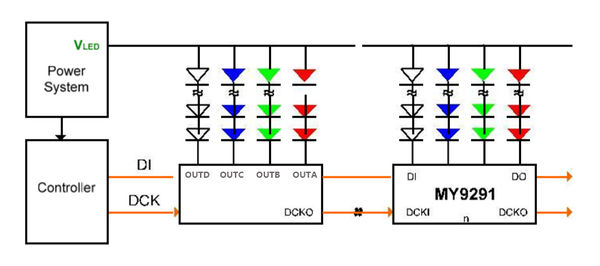
OpenLight 采用台湾明阳 4 通道恒流 LED 驱动芯片,控制 R, G, B, W 四路 LED 灯珠
- Feature:
- 3.3 - 5V 电源电压范围(±10%)
- 每个通道 5 - 350 mA 恒流输出范围
- 可承受最大输出电压 24V,支持多颗 LED 串联
- 外接器件少,仅需四个外接电组来设定四組恆流电流
- Block Diagrame:
电源为恒压源,可以多片级联,MCU 的控制线就两个:DI 和 DCK
- 电源电压与灯珠串并联确定:
- 12V 电源的情形,如选用 VF 为 3V 左右的 LED 灯珠,则需要 4 颗串联,这样每颗灯珠分到电压为 3V 左右;2V 左右的灯珠,则需要 6 颗串联
- 24V 电源,则 3V 灯珠 8 颗串联,2V 灯珠 12 颗串联
- 6V 电源,则 3V 灯珠 2 颗串联,2V 灯珠 3 颗串联
- 输出限流
MY9291 单路最大输出 350mA,为节约灯珠寿命,可限制通过灯珠的最大电流以节约灯珠寿命
最大输出电流限制:
R = 380mV / Iout
满输出 350mA,则每路的限流电阻都得选为:1R,1/4 W 够用
OpenLight 球泡灯,R/G/B 选用电阻 4R7,限流为 81mA 左右,W 用两个 4R7 并联 2.35R 左右,限流为 162mA 左右。这样基本限制经过每颗 5730 (0.5W) 灯珠的电流为 80mA 左右,以延迟灯珠老化。这样整体功率被限制在 5W,如要增加亮度,可将这 5 个 4R7 电阻替换为 3R0,可将输出功率增加到 7W
6 Power
6.1 12V
220V 转 12V 恒压电源模块,额定 12W,1A 电流输出
6.2 3.3V
ESP8266/ESP8285 chip、MY9291/MY9231 chip、SPI Flash chip are all 3.3V power.
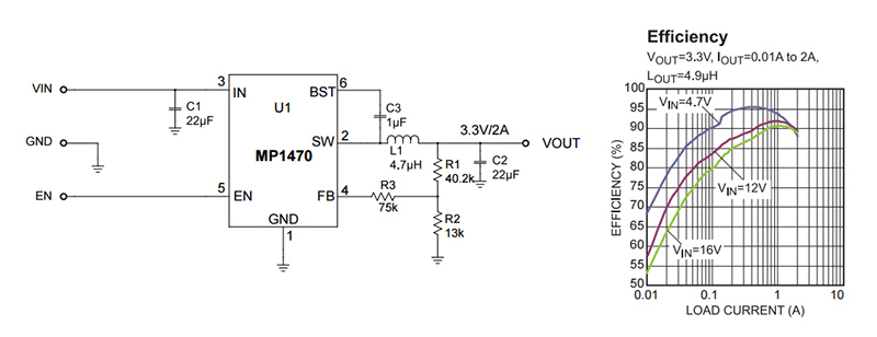
6.2.1 MP1470
- Wide 4.7V to 16V Operating Input Range
- Fixed 500kHz Switching Frequency
- Over-Current Protection and Hiccup
- Thermal Shutdown
- Output Adjustable from 0.8V
- Available in a 6-pin TSOT-23 package
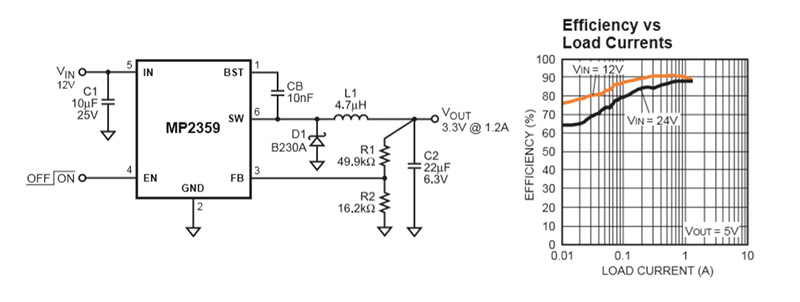
6.2.2 MP2359
- Wide 4.5V to 24V Operating Input Range
- 1.2A Peak Output Current
- 0.35Ω Internal Power MOSFET Switch
- Stable with Low ESR Output Ceramic Capacitors
- Up to 92% Efficiency
- 0.1μA Shutdown Mode
- Fixed 1.4MHz Frequency
- Thermal Shutdown
- Cycle-by-Cycle Over Current Protection
- Output Adjustable from 0.81V to 15V
